In addition due to self inductive and mutual inductive effects ie. Muratas lineup of inductors for high frequency circuits features ultra compact film type inductors general purpose multilayer inductors and high q high current supporting wire wound type inductors all of which are used in high frequency circuits.

L 07w5n6jv4t Johanson Technology Rf Wirewound Chip

How To Choose Right Inductors For A Matching Circuit

A New Process For On Chip Inductors With High Q Factor
The program calculates the inductance of different species of inductor design.

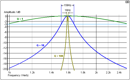
Optimal q of inductor. The quality factor or q of an inductor is the ratio of its inductive reactance to its resistance at a given frequency and is a measure of its efficiency. The higher the q factor of the inductor the closer it approaches the behavior of an ideal inductor. Inductor consists of a number of series connected metal segments.
The q factor can be applied to an inductor just as it can to a resonant circuit containing inductance capacitance and resistance. In each segment time varying conductive current will flow due to a time varying voltage impressed on the segment. Often inductors may be thought of as having a pure inductance whereas in reality they have some resistance.
G da 5 where p p 1 ql 1 2 the parameters for p are dependant on the cmos tech nology but typically a is assumed to be 08 1 take to be 09 d is set to 2 3 times the value of normally 4 is set between 2 3 normally 2 g g 267 0162 1 ql 1 0162 54 409 p 2. Coil32 allows estimating q factor of rf single layer air core inductor. Miller through hole toroid inductors 814 eic1452.
It is very important that the inductor has optimal design meaning optimal geometry with the best possible characteristics 1. As a general rule q in a rf inductor peaks with a form factor ld between 1 and 4. The reason optimum form factors vary with high external capacitance any reasonable amount of internal stray capacitance shunting the inductor only causes a very small change in circulating current in the inductor.
This procedure is employed to derive the equations governing. Optimal single resistor damping of input filters robert w. It is possible to select an optimal variant to use available coil former or recalculate inductor to other dimensions.
Our computer aided optimization technique using geometric programming gp has been used to find the optimum design for spiral inductors with different layout 2 4. Erickson colorado power electronics center university of colorado boulder colorado 80309 0425 rwe at bouldercoloradoedu abstracta general procedure is outlined for optimizing the damping of an input filter using a single resistor. 42 optimal q of inductor optimal q is given by.
Selecting the optimal inductor for power converter applications sdr series power inductors smd non shielded srn series power inductors smd semi shielded srp series power inductors smd high current shielded srr series power inductors smd shielded sru series power inductors smd shielded jw. This resistance causes energy loss and hence the inductor q is reduced. 43 evaluation of lg.
Layout of a typical square spiral inductor. An inductor q is a valuable quantity.

When To Use An Rf Choke Vs An Inductor Analog Technical

Inductance Calculation And Layout Optimization For Planar

Fixed Inductors Motley Electronic Topics Eewiki

Current Ripple Factor Of A Buck Converter Richtek Technology

Rf Integrated Inductor Modeling And Its Application To

Ferrite Beads Demystified Analog Devices

Metal Inductors And Trends In Power Supplies Tech Info
Lineup Of Lqw Series Of Wire Wound Type Rf Radio Frequency

Coil32 The Coil Inductance Calculator

Frequency Dependences Of The Inductance L And The Quality

Abracon Rf Inductors

Lc Circuit Bigger L Than C Or Bigger C Than L
Comments
Post a Comment